CheckPoint Remote Access VPN Caveats

a4dvqjud9ne31.jpg

Endpoint Security vs. Mobile Access vs. SecuRemote

This is the first and foremost headache you’ll run in to.  Mac only supports Endpoint Security, but Windows clients will have 3 options.   The descriptions aren’t very helpful y as “Enterprise Grade” smells like a marketing term that doesn’t help anyone make a decision.

CheckPointVPNClientWindowsInstall

So here’s a quick breakdown:

  • Checkpoint Endpoint Security requires endpoint security on management server
  • CheckPoint Mobile uses the Mobile access blade and thus licensing
  • SecuRemote does not require a license, but does not support Office Mode

So they key take-away on Endpoint Security VPN vs. Check Point Mobile are fundamentally the same feature-wise, but work on different licensing models.

When to use Office Mode?

The main benefit of Office Mode is it mitigates IP conflict between a user’s home/office network and the VPN domain.  For example, say the user’s workstation is on 192.168.1.0/24 and 192.168.0.0/16 is to be routed via the VPN.  Since the client will simply show up as 10.10.10.100 or whatever for the CheckPoint, this will clash with the topology and the client will be disconnected after a few seconds.

The easy workaround for this problem not using Office Mode is only route very specific internal traffic via the VPN.

VPN Client IP address pool

By default, VPN client IP are controlled by this object:

CP_default_Office_Mode_addresses_pool = 172.16.10.0/24

An automatic NAT rule to hide behind the gateway will be enabled as well, so it’s usually OK to leave this as is.  But, it can be changed at the gateway level under VPN Clients -> Office Mode

Split Tunnel network list

CheckPoint calls this the VPN domain.  By default, it’s generated via the topology, which is a combination of interfaces and routes.  It can instead be manually set on the gateway under Network Management -> VPN Domain.


Common VPN Client Problems

Uninstalling Endpoint Security version 81.10 on Windows 10 horks all network adapters

https://community.checkpoint.com/t5/Remote-Access-Solutions/Lost-network-connectivity-uninstalling-Endpoint-VPN/m-p/25650/highlight/false

Workaround is to install/uninstall and older client version such as 80.89

Can’t install client on Windows 10 version 1803

Installation fails with ugly error message “An error occurred during the installation of assembly “Microsoft.VC80.ATL, type=”win32”, version “8.0.50727.42”

CheckPointSecuremoteWindowsInstallFail

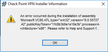
This is a known issue that can be caused by an incomplete Microsoft .NET library installation.

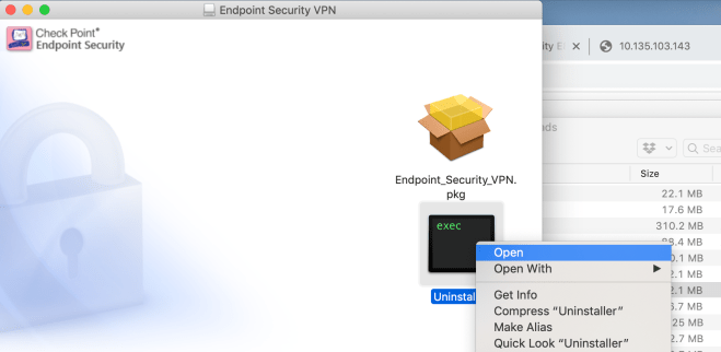
Can’t uninstall Mac Client

Simply dragging to the trash won’t fully un-install the client.  Instead, Re-open the .dmg file and Ctrl + click the black and green Uninstaller icon, then Select Open

CheckPointMacVPNClientUninstall

Clients connect to the gateway’s Internal IP address

This is usually because the gateway is behind NAT, referenced by internal IP address in SmartConsole, and Link selection is using the main IP address, which is the default.

The fix is under IPSec VPN -> Link selection.  Put the public IP address as the statically NAT’d IP and the clients will then stay connected to the public IP address.

Clients connect, but can’t access anything, then drop a few second later

In my case this this was due to giving the VPN clients a 10.X.X.X address but having a route to 10.0.0.0/8 via the internal interface, which triggered anti-spoofing rules:

@;2251823;[cpu_0];[fw4_1];fw_log_drop_ex: Packet proto=1 10.135.200.81:2048 -> 10.135.202.161:33536 dropped by fw_antispoof_log Reason: Address spoofing;
@;2251849;[cpu_0];[fw4_1];fw_log_drop_ex: Packet proto=17 10.135.200.81:18011 -> 10.135.202.199:18234 dropped by fw_antispoof_log Reason: Address spoofing;
@;2251849;[cpu_0];[fw4_1];fw_log_drop_ex: Packet proto=17 10.135.200.81:18012 -> 10.135.202.199:18234 dropped by fw_antispoof_log Reason: Address spoofing

The simple solution is disable spoofing on the external interface.

An alternate work-around is choose IP address for the VPN clients that are outside the internal interface’s topology.  I used 198.51.100.0/24.  This also fixes the route conflicts described above under “Office Mode”

After initial connection, VPN Client caches gateway’s internal IP address

This will happen when the Checkpoint gateway is behind a NAT.  The fix is provide the external IP address under Gateway -> IPSec VPN -> Link Selection “Always use this address” and enter the external IP in the “Statically NATed IP” field.

Client complains VPN-1 Server could not find any certificate for use for IKE

Means the connection is expecting the client to authenticate via certificate.  Quickest fix: on the gateway under VPN Clients -> Authentication, set the Authentication Method to “Username and password”

Common Gateway/SmartConsole problems not related to VPN

Can’t SSH to gateway after hooking in to SmartConsole

Unlike the Web Admin access, which is implicit, SSH has to be explicitly allowed in the policy.  This is true even when using the dedicated management route feature in R80.30

Palo Alto User Identification and Group Mapping Caveats

I wanted to write a firewall rule to allow only Active Directory group(s) to access a given zone, destination IP, or service.  Since the users would be connected directly to the Palo Alto via GlobalProtect, user tracking was already happening.  The clients are in source zone “Trust” and user identification was already checked.

I followed the steps in this KB article to configure group mapping but found two major gotchas.  In the Authentication Profile, the user domain must be entered.  After doing this, users began showing up as domain\username rather than just username.  Secondly, in the group mapping configuration, user domain needed to be blank.

I can now write a rule with mydomain\group as the source user.

Common gotchas

In the source zone, make sure the User-ID option is checked.

PaloaltoZoneUserIdentification

In Device -> Server Profiles -> LDAP, set the base DN to something at a higher level than all the groups, and set the Bind DN to an account with privileges to lookup group membership.

PaloAltoLDAPServerProfile

In Device -> Authentication Profile, set User Domain to the abbreviated AD domain

PaloAltoAuthProfile

Under Device -> User Identification -> Group Mapping Settings tab, leave the User Domain field blank.

PaloaltoUserIDGroupMapping

Useful troubleshooting commands

Check user to IP address mapping table

show user ip-user-mapping all

Get list of LDAP groups

show user group-mapping state all

Check group membership for a certain LDAP group

show user group name mydomain\myGroup


Launching Checkpoint Gateway in AWS

Instance types for R80.20 or higher:

  • Checkpoint Gateway: c5.large  (2 vCPU / 4 GB) or c5.xlarge (4 vCPU / 8 GB)
  • Checkpoint Manager: m5.large ( 2vCPU / 8 GB) or m5.xlarge ( 4 vCPU / 16 GB)

Once launched, SSH in and set a temporary admin password:

$ ssh -i ~/.ssh/mykey.pem admin@10.10.10.123
This system is for authorized use only.
In order to configure your system, please access the Web UI and finish the First Time Wizard.

gw-f0633c> set user admin password
New password:
Verify new password:
gw-f0633c> save config

I also like to add routes so the Internal interface is accessible:

gw-f0633c> set static-route 10.0.0.0/8 nexthop gateway address 10.10.10.1 on
gw-f0633c> set static-route 172.16.0.0/12 nexthop gateway address 10.10.10.1 on
gw-f0633c> set static-route 192.168.0.0/16 nexthop gateway address 10.10.10.1 on
gw-f0633c> save config

Now access the GUI.  In this case, https://10.10.10.123

Route Filtering and Aggregation in Hybrid Cloud scenarios (EIGRP -> BGP)

One of the challenges of cloud is route table limits .  For example, AWS has a limit of 100 per table.  This can pose a real challenge in hybrid cloud scenarios where the on-prem infrastructure can easily support hundreds or thousands of internal routes no problem, leaving you (aka “cloud guy”) responsible for performing filtering and aggregation.

Consider this scenario:

EIGRPtoBGPredistribution

The CSR1000v learns about 150 routes via EIGRP, mostly in RFC 1918 space:

D EX 10.4.0.0/16 [170/51307520] via 10.1.4.73, 00:05:02, Tunnel100
D EX 10.5.0.0/16 [170/51307520] via 10.1.4.61, 00:05:02, Tunnel100
D EX 10.6.8.0/22 [170/51307520] via 10.1.4.12, 00:05:02, Tunnel100
D EX 192.168.11.0/24 [170/52234240] via 10.1.4.88, 00:05:02, Tunnel100
D EX 192.168.22.0/23 [170/51829760] via 10.1.4.99, 00:05:02, Tunnel100
D EX 192.168.33.0/24 [170/51824640] via 10.1.4.123, 00:05:02, Tunnel100

So obviously we need need to do some filtering or summarization before passing the routes to the AWS route tables via BGP.

The quick and simple fix: summarize the 10.0.0.0/8 & 192.168.0.0/16 prefixes on the CSR1000v:

router bgp 65000
 bgp log-neighbor-changes
 !
  address-family ipv4 
  aggregate-address 10.0.0.0 255.0.0.0 summary-only  
  aggregate-address 192.168.0.0 255.255.0.0 summary-only
  redistribute eigrp 100
  neighbor 169.254.1.2 remote-as 65100
  neighbor 169.254.1.2 activate

Upon initial examination, this seems to work great.  Only the aggregate routes are passed to the BGP neighbors:

CSR1000v#sh ip bgp nei 169.254.1.2 advertised-routes | inc (10\.|192\.168)
*>  10.0.0.0         0.0.0.0       32768 i
*>  192.168.0.0/16   0.0.0.0       32768 i

But there’s a nasty surprise when the EIGRP neighbors are reset.  The “summary-only” option briefly stops working for about 20 seconds:

CSR1000v#sh ip bgp nei 169.254.1.2 advertised-routes | inc 10\.
*> 10.0.0.0      0.0.0.0              32768 i
*> 10.4.0.0/16   10.1.4.73  51307520  32768 ?
*> 10.5.0.0/16   10.1.4.61  51307520  32768 ?
*> 10.6.8.0/22   10.1.4.12  51307520  32768 ?
*> 10.7.12.0/22  10.1.4.52  51307520  32768 ?
*> 10.8.8.0/24   10.1.4.7   51307520  32768 ?
*> 10.9.0.0/24   10.1.4.41  51307520  32768 ?
*> 10.77.0.0/16  10.1.4.8   51312640  32768 ?

This exceeds the 100 route limit, and AWS will disable the BGP peering session for 5 minutes.

One fix is use filters instead of the “summary-only” option:

router bgp 65000
 bgp log-neighbor-changes
 !
 address-family ipv4
  aggregate-address 10.0.0.0 255.0.0.0
  aggregate-address 172.16.0.0 255.240.0.0
  aggregate-address 192.168.0.0 255.255.0.0
  redistribute eigrp 100
  distribute-list prefix SUMM_RFC_1918 out
!
ip prefix-list SUMM_RFC_1918 seq 10 deny 10.0.0.0/8 ge 9
ip prefix-list SUMM_RFC_1918 seq 20 deny 172.16.0.0/12 ge 13
ip prefix-list SUMM_RFC_1918 seq 30 deny 192.168.0.0/16 ge 17
ip prefix-list SUMM_RFC_1918 seq 99 permit 0.0.0.0/0 le 32

Another solution is simply don’t do EIGRP to BGP redistribution, and instead just advertise the RFC 1918 blocks with the network statement:

router bgp 65000
 bgp log-neighbor-changes
 !
 address-family ipv4 
  network 10.0.0.0
  network 172.16.0.0 mask 255.240.0.0
  network 192.168.0.0 mask 255.255.0.0
!
ip route 10.0.0.0 255.0.0.0 Null0 254
ip route 172.16.0.0 255.240.0.0 Null0 254
ip route 192.168.0.0 255.255.0.0 Null0 254

SSHing to an older Cisco ASA from a new Mac

Newer SSH clients such as on MacOS 10.14 (Mojave) may not want to use the old key sizes and cipher suites on an ASA.

One error message is about key exchange parameters:

no matching key exchange method found. Their offer: diffie-hellman-group1-sha1

Can fix this by using the older key exchange algorithm as an command line option:

ssh -oKexAlgorithms=+diffie-hellman-group1-sha1 username@myasa.com

This can then be fixed server-side on the ASA by configuring Group 14 (2048-bit keys)

ASA(config)# ssh key-exchange group ?
configure mode commands/options:
  dh-group1-sha1   Diffie-Hellman group 2
  dh-group14-sha1  Diffie-Hellman group 14
ASA(config)# ssh key-exchange group dh-group14-sha1

Likewise may get messages about cipher suites not matching:

no matching cipher found. Their offer: aes128-cbc,3des-cbc,aes192-cbc,aes256-cbc

Workaround is to specify ciphers as an option to SSH:

ssh -c aes128-cbc,3des-cbc username@myasa.com


IPSec VPNs on Cisco routers when both are behind NAT

IPSec VPNs or really any site-to-site VPN works best when at least one of the sides or better yet both have Public IP addresses.  But what if one is behind NAT, or even both?  It gets increasing tricky to configure the correct IP addresses for authentication, and forward correct ports on protocols.  As I recently discovered, using IKEv2 and/or GRE further complicates things.  Consider this setup:

IPSecVPNsBehindNATs

Both routers are behind NAT/PAT firewalls without static 1-to-1 NATs configured.  There are still some requirements though:

  • Both firewalls must allow for protocol 50 passthrough for IPSec, or protocol 47 passthough if using GRE, which most do
  • At least one side must be forwarding ports udp/500 (isakmp) and udp/4500 (nat-t) to the router’s internet-facing interface so the connection can be established
  • Both routers need crypto ipsec nat-transparency udp-encapsulation enabled, which is the default setting.  

Let’s look at sample configs for each scenario.  These assume 1921 ISR G2 routers but IOS-XE configs should be exactly the same.

IPSec with ISAKMP / IKEv1

The is the simplest way to do it since only public IPs need to be referenced.

1) The ISAKMP portion:

crypto isakmp invalid-spi-recovery
crypto isakmp disconnect-revoked-peers
crypto isakmp keepalive 10 crypto isakmp nat keepalive 900 ! Policy supporting strong encryption crypto isakmp policy 100 encr aes 256 ! 256-bit AES encryption hash sha384 ! SHA-384 hashing authentication pre-share ! Using pre-shared keys lifetime 28800 ! 28000 seconds = 8 hours group 14 ! group 14 = 2048 bit key
! Backup policy supporting weaker encryption support for older devices crypto isakmp policy 200 encr aes ! 128-bit AES encryption hash sha ! SHA-1 hashing authentication pre-share ! Using pre-shared keys lifetime 28800 ! 28000 seconds = 8 hours group 2 ! group 2 = 1024 bit key ! FYI - default values are still des, sha, rsa-sig, 86400, group 1 :-O

2) And then pre-shared keys:

! Key for site 1 router
crypto keyring Site2
  local-address GigabitEthernet0/0
  pre-shared-key address 203.0.113.222 key 0 MySecretKey

! Key for site 2 router
crypto keyring Site1
 local-address GigabitEthernet0/0
 pre-shared-key address 198.51.100.111 key 0 MySecretKey

! Can also use "crypto isakmp key 0 MySecretKey address 1.2.3.4"

3) IPSec parameters.  For encryption, I like to just use 128-bit AES with either SHA-256 or SHA-1 signing with a group 2 (1024-bit) key to make the tunnel negotiation quick as possible.

! Create some IPSec Transform sets for ESP & 128-bit AES
crypto ipsec transform-set ESP_AES128_SHA256 esp-aes esp-sha256-hmac 
 mode tunnel
crypto ipsec transform-set ESP_AES128_SHA esp-aes esp-sha-hmac 
 mode tunnel

! Create IPSec profile
crypto ipsec profile MY_IPSEC_PROFILE
 set transform-set ESP_AES128_SHA256 ESP_AES128_SHA 
 set pfs group2    ! group 2 = 1024-bit key

Optional step: since the “client” side isn’t reachable on port udp/500, the “server” side may be configured as a responder.  This cuts down superfluous traffic, especially when the client is unreachable.

crypto ipsec profile IPSEC_PROFILE
 responder-only

5) The last step is build the tunnel interfaces.  For the “client” side:

interface Tunnel1000
 ip address 169.254.0.1 255.255.255.252
 ip tcp adjust-mss 1379
 keepalive 10 3
 tunnel source GigabitEthernet0/0
 tunnel mode ipsec ipv4
 tunnel destination 203.0.113.222
 tunnel protection ipsec profile IPSEC_PROFILE

Server side is exactly the same but with different IP addresses:

interface Tunnel1000
 ip address 169.254.0.2 255.255.255.252
 tunnel destination 198.51.100.111

Doing debug crypto isakmp on the server side while the tunnels come up shows the public IP address of the client.  Note the client’s random source ports.

ISAKMP (0): received packet from 198.51.100.111 dport 500 sport 14972 Global (R) MM_SA_SETUP
ISAKMP (1003): received packet from 198.51.100.111 dport 4500 sport 51597 Global (R) MM_KEY_EXCH
ISAKMP:(1003):SA has been authenticated with 198.51.100.111
ISAKMP:(1003):Detected port floating to port = 51597

We never see client’s private IP, but we do see the server side’s private IP at the end when the SA is finally built:

ISAKMP:(1003): Process initial contact,
bring down existing phase 1 and 2 SA's with local 192.168.2.222 remote 198.51.100.111 remote port 51597
ISAKMP: Trying to insert a peer 192.168.2.222/198.51.100.111/51597/, and inserted successfully

Can also see the other site’s private IP by examining the SAs once built:

Site1#show crypto isakmp peers 203.0.113.222
Peer: 203.0.113.222 Port: 4500 Local: 192.168.1.111
Phase1 id: 192.168.2.222

Site2#show crypto isakmp peers 198.51.100.111
Peer: 198.51.100.111 Port: 51597 Local: 192.168.2.222
Phase1 id: 192.168.1.111


IPSec with IKEv2

IKEv2 is new to me, but it was a surprise to see slightly different behavior when using NAT. Run through of the configuration:

1) Set some global IKEv2 parameters

crypto logging ikev2
crypto ikev2 nat keepalive 900
crypto ikev2 dpd 10 2 periodic

2) Create an IKEv2 Proposal and Policy

3) Keys are defined in the IKEv2 keyring, which has each site’s public IP address:

crypto ikev2 keyring MY_IKEV2_KEYRING
 ! Use this on site 1 router
 peer Site2
  address 203.0.113.222
  pre-shared-key MySecretKey1234    ! Must be 16 chars or longer
 ! Use this on site 2 router
 peer Site1
  address 198.51.100.111
  pre-shared-key MySecretKey1234    ! Must be 16 chars or longer

4) Create IKEv2 Profile

crypto ikev2 profile MY_IKEV2_PROFILE
 match address local interface GigabitEthernet0/0
 match identity remote address 192.168.0.0 255.255.0.0
 authentication remote pre-share
 authentication local pre-share
 keyring local MY_IKEV2_KEYRING
 dpd 20 2 periodic

This is where is gets weird because the “remote address” parameter needs to match the internal IP address(es) of the other sides.  The simple and lazy approach is use 0.0.0.0 since that will match anything.  The other option is use a different profile for each peer.

5) Add IKEv2 profile to the existing IPSec profile.  Note that doing so shouldn’t break IKEv1 clients as the IKEv2 stuff should just be ignored.

crypto ipsec profile MY_IPSEC_PROFILE
 set transform-set ESP_AES128_SHA256_TUNNEL ESP_AES128_SHA1_TUNNEL 
 set pfs group2
 set ikev2-profile MY_IKEV2_PROFILE

In the SAs, we can see our private IP,  but not the other side’s:

Site1#show crypto ikev2 sa remote 203.0.113.222
Tunnel-id Local                 Remote                fvrf/ivrf            Status
1         192.168.1.111/4500    203.0.113.222/4500    none/none            READY  
      Encr: AES-CBC, keysize: 128, Hash: SHA256, DH Grp:14, Auth sign: PSK, Auth verify: PSK
      Life/Active Time: 86400/30 sec

Site2#sh crypto ikev2 sa remote 198.51.100.111      
Tunnel-id Local                 Remote                fvrf/ivrf            Status 
1         192.168.2.222/4500    198.51.100.111/51597  none/none            READY  
      Encr: AES-CBC, keysize: 128, Hash: SHA256, DH Grp:14, Auth sign: PSK, Auth verify: PSK
      Life/Active Time: 86400/71 sec

BTW, if NAT-T has been disabled but is required by the other end, debug crypto ikev2 will show this:

Oct 12 19:53:08.620: IKEv2-ERROR:(SESSION ID = 1075,SA ID = 2): NAT is found but it is not supported.: NAT-T disabled via cli
Oct 12 19:53:08.620: IKEv2-ERROR:(SESSION ID = 1075,SA ID = 2):: NAT-T disabled via cli

IKEv2 Policies, Proposals, and Profiles on Cisco Routers

Just like “crypto isakmp policy”, the “crypto ikev2 policy” configuration is global and cannot be specified on a per-peer basis.  If there’s a mismatch, “debug crypto ikev2 error” will show something like this:

IKEv2-ERROR:(SESSION ID = 685,SA ID = 1):Expected Policies: : Failed to find a matching policyProposal 1: AES-CBC-128 SHA256 SHA256 DH_GROUP_2048_MODP/Group 14

There are two solutions.  The simplest is specify all possible encryption, integrity, and PFS parameters in a single proposal:

crypto ikev2 proposal MY_IKEV2_PROPOSAL 
 encryption aes-cbc-256 aes-cbc-192 aes-cbc-128 3des
 integrity sha512 sha384 sha256 sha1
 group 21 20 19 16 14 5 2

crypto ikev2 policy MY_IKEV2_POLICY 
 proposal MY_IKEV2_PROPOSAL

Alternately, write separate proposals, then list them in the policy by preference:

crypto ikev2 proposal HIGH 
 encryption aes-cbc-256 aes-cbc-192 aes-cbc-128 
 integrity sha512 sha384 sha256 
 group 21 20 19
crypto ikev2 proposal MEDIUM
 encryption aes-cbc-256 aes-cbc-192 aes-cbc-128 
 integrity sha256 sha1
 group 16 14
crypto ikev2 proposal LOW 
 encryption aes-cbc-128 3des
 integrity sha1 md5
 group 5 2
crypto ikev2 policy MY_IKEV2_POLICY 
 proposal HIGH
 proposal MEDIUM
 proposal LOW

It’s disappointing Cisco did not design things so policies could be associated with individual peers.   Imagine a router terminating VPNs to different business partners, where Partner A insists on AES256/SHA512/Group16, while Partner B is still doing 3DES/MD5/Group2.  You would write the policy with the most secure at the top, but there’s nothing to stop partner A from downgrading to partner B’s policy.  It’s a security concern, plus takes extra time to negotiate.

Palo Alto Firewalls supports different ISAKMP policies on a per-IKE gateway basis and it’s one of the reasons I’ve really preferred them for Site-to-Site VPNs over the years.

SYSMGR-2-CFGWRITE_ABORTED_CONFELEMENT_RETRIES

15 minutes on a Cisco Nexus 9k and already found a cute bug.

SYSMGR-2-CFGWRITE_ABORTED_CONFELEMENT_RETRIES: Copy R S failed as config-failure retries are ongoing. Type "show nxapi retries" for checking the ongoing retries
# show nxapi retries
#1. Dn: sys/vpc/inst/dom/keepalive, Operation: modify, Src: vpc bmp: 0x4.

Quickest stupid work-around I could find:

# copy running-config bootflash:latestconfig.txt
# copy bootflash:latestconfig.txt startup-config 
# reload

And there’s a similar looking bug:

# copy run start
[########################################] 100%
Configuration update aborted: request was aborted


FortiGate Initial Config via CLI

Configure Network Interfaces

Example:

  • Set wan1 interface to static IP address 198.51.100.244/255.255.255.240
  • Configured default route of 198.51.100.241.
  • Allow ping and HTTPS on wan1 interface
  • Set LAN interface to 192.168.100.1/255.255.255.192
  • Set LAN interface’s DHCP scope address range as 192.168.100.30-59
  • Change lease time from default of 7 days to 2 hours
config system interface
 edit wan1
  set mode static
  set ip 198.51.100.244/28
  set allowaccess ping https fgfm
 next
 edit lan
  set ip 192.168.100.1/26
 end
config router static
 edit 0 
  set gateway 198.51.100.241
  set distance 1
  set device wan1
 end
config sys dhcp server
 edit 1
  set default-gateway 192.168.100.1
  set netmask 255.255.255.192
  set lease-time 7200
  config ip-range
   edit 1
    set start-ip 192.168.100.30
    set end-ip 192.168.100.59
   end
  end

Other useful commands

Change the admin user password:

config system admin
 edit admin
 set password MyNewPassword end

Create a secondary admin user

config system admin
    edit secondadminusername
      set accprofile super_admin
      set password MyPasswordGoesHere

Get L1 and L3 status of all interfaces

get system interface physical

Disabled/Enable an interface

config system interface
 edit lan
  set status down
 next
 edit lan
  set status up
 end

Enable sending of LLDP information

config system global
    set lldp-transmission enable
end

Check the route table

get router info routing-table all

Check the ARP Table

get system arp

Get the software version and serial number

get system status

Ping something

execute ping 8.8.8.8

Reboot the firewall

execute reboot


Authentication to Synology Directory Server (LDAP Server)

Upon configuring Directory Server the Synology will provide something like this:

The password configured is password for the ‘root’ user

Configuration for Cisco ASA / AnyConnect

aaa-server SYNOLOGY protocol ldap
aaa-server SYNOLOGY (Inside) host 192.168.1.100
 ldap-base-dn dc=myserver,dc=mydomain,dc=com
 ldap-scope subtree
 ldap-naming-attribute uid
 ldap-login-password <root user password>
 ldap-login-dn uid=root,cn=users,dc=myserver,dc=mydomain,dc=com
 server-type auto-detect

Configuration for FortiGate GUI

  • Common Name Identifier = uid
  • Distinguished Name = cn=users,dc=myserver,dc=mydomain,dc=com
  • Bind Type = Simple

Configuration for F5 BigIP

Need to change Authentication from ‘Basic’ to ‘Advanced’ to set Login LDAP attribute

  • Remote Directory Tree: dc=myserver,dc=mydomain,dc=com
  • Scope: Sub
  • BIND DN: uid=root,cn=users,dc=myserver,dc=mydomain,dc=com
  • Password: <root user password>
  • User Template: uid=%s,cn=users,dc=myserver,dc=mydomain,dc=com
  • Login LDAP Attribute: uid

To use Remote Role Groups:

Attribute String: memberOf=cn=users,cn=groups,dc=myserver,dc=mydomain,dc=com