Had a simple but time-consuming problem today. Our Cisco IOS-XE 16.12 routers authenticate to AD via RADIUS to Microsoft NPS, with certain AD group(s) having admin privileges. On the router side, configuration looks like this, where 10.10.10.10 is the NPS server:
aaa group server radius MyRADIUS
 server-private 10.10.10.10 auth-port 1812 acct-port 1813 key 0 abcd1234
 ip vrf forwarding Mgmt-intf
!
aaa new-model
aaa session-id common
!
aaa authentication login default local group MyRADIUS
aaa authentication enable default none
aaa authorization config-commands
aaa authorization exec default local group MyRADIUS if-authenticated
In NPS, I have a policy to match the appropriate Windows Group with Authentication Type = PAP and NAS Port Type = Virtual. In the Settings tab, I then have this Vendor Specific RADIUS Attribute:
This allows users in this group to SSH to any router and immediately have privilege level 15, which gives them full admin access.
Now and I needed to give a certain AD group read-only access to view running-configuration. So I create a new policy matching to that AD group, and in the RADIUS attributes, under Vendor Specific, I add this one:
The test account could then SSH to the router and verify privilege level was 7:
Router#show priv
Current privilege level is 7
I then downgraded privileges on each router so that only level 3 was required to view running-config:
privilege exec level 3 show running-config view full
privilege exec level 3 show running-config view
privilege exec level 3 show running-config
privilege exec level 3 show
But, when doing “show running-config”, they would just get a nothing back in return. As it turns out I needed one more step; lowering the privilege for viewing files on the router
file privilege 3
Now it works:
Router#show running-config view full
Building configuration...

Current configuration : 15124 bytes
!
! Last configuration change at 15:39:15 UTC Tue Mar 17 2020 by admin
! NVRAM config last updated at 15:39:21 UTC Tue Mar 17 2020 by admin
!
version 16.12
service timestamps debug datetime msec
service timestamps log datetime localtime show-timezone
service password-encryption
no service dhcp
service call-home
Let’s say you have a web server behind a load balancer that acts as a reverse proxy. Since the load balancer is likely changing the source IP of the packets with its own IP address, it stamps the client’s IP address in the X-Forwarded-For header and then passes it along to the backend server.
Assuming the web server has been configured to log this header instead of client IP, a typical log entry will look like this:
198.51.100.111 is the client’s IP address, and 203.0.113.222 is the Load Balancer’s IP address. Pretty simple. One would assume that it’s always the first entry that’s the client’s IP address, right?
Well no, because there’s an edge case. Let’s say the client is behind a proxy server that’s already stamping X-Forward-For with the client’s internal IP address. When the load balancer receives the HTTP request, it will often pass the X-Forwarded-For header unmodified to the web server, which then logs the request like this:
192.168.1.49 is the client’s true internal IP, but we don’t care about that since it’s RFC-1918 and not of any practical use. So it’s actually the second to last entry (not necessarily the first!!!) that contains the client’s public IP address and the one that should be used for any Geo-IP functions.
Here’s some sample Python code:
#!/usr/bin/env python

import os

x_fwd_for = os.environ.get('HTTP_X_FORWARDED_FOR', '')

if ", " in x_fwd_for:
    client_ip = x_fwd_for.split(", ")[-2]
else:
    client_ip = os.environ.get('REMOTE_ADDR', '127.0.0.1')
If behind NGinx, a better solution is to prefer the X-Real-IP header instead:
import os

x_real_ip = os.environ.get('HTTP_X_REAL_IP', '')
x_fwd_for = os.environ.get('HTTP_X_FORWARDED_FOR', '')

if x_real_ip:
    client_ip = x_real_ip
elif x_fwd_for and ", " in x_fwd_for:
    client_ip = x_fwd_for.split(", ")[-2]
else:
    client_ip = os.environ.get('REMOTE_ADDR', '127.0.0.1')
Other platforms can easily be configured to stamp an X-Real-IP header as well. For example, on an F5 BigIP LTM load balancer, this iRule will do the job:
when HTTP_REQUEST {
    HTTP::header insert X-Real-IP [IP::remote_addr]
}
By default, the CheckPoint will usually have three dynamic objects that can be referenced in firewall and NAT policy rules
LocalGateway – Main interface of the CheckPoint
LocalGatewayExternal – External interface of the CheckPoint
LocalGatewayInternal – First internal interface of the CheckPoint
In a 3-Nic deployment, you may want to reference the second internal NIC, for example to source NAT traffic bound to the internal servers to the CheckPoint’s internal IP address.
To do this, you must create a custom dynamic object in SmartConsole, then manually create it on each gateway.
On the gateway, first verify the internal IP address:
[Expert@gateway]# dynamic_objects -n LocalGateway-eth2 -r 10.1.2.1 10.1.2.1 -a
Verify it’s been created:
[Expert@gateway]# dynamic_objects -l

object name : LocalGateway
range 0 : 198.51.100.100 198.51.100.100

object name : LocalGatewayExternal
range 0 : 198.51.100.100 198.51.100.100

object name : LocalGatewayInternal
range 0 : 10.1.1.10 10.1.1.10

object name : LocalGateway-eth2
range 0 : 10.1.2.1 10.1.2.1
Healthchecks are failing, even though the service is running and open via fw rules
Healthchecks actually originate from GCP directly, rather than the load balancer instance itself. So these networks must be whitelisted in the firewall rules:
35.191.0.0/16
130.211.0.0/22
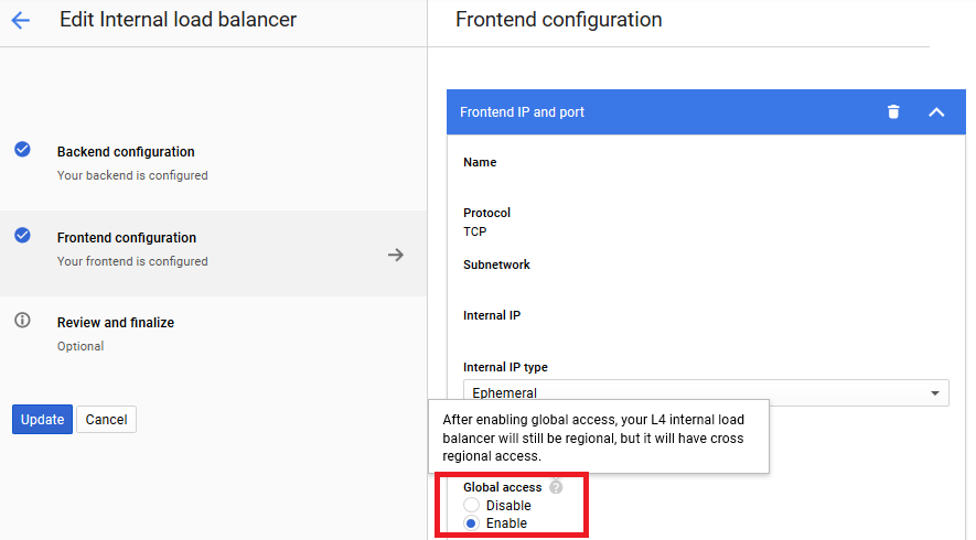
The LB works in the same region, but does not respond from different regions
By default, load balancers operate in regional-only mode. To switch to global, edit the frontend properties and look for this radio button:
A minimum 3 NICs are required and will be broken down like so:
eth0 – Public / External Interface facing Internet
eth1 – Management interface used for Cluster sync. Can also be used for security management server communication
eth2 – First internal interface. Usually faces internal servers & load balancers. Can be used for security management server communication
The Deployment launch template has a few fields which aren’t explained very well…
Security Management Server address
A static route to this destination via management interface will be created a launch time. If the Security Management server is accessed via one of the internal interfaces, use a dummy address here such as 1.2.3.4/32 and add the static routes after launch.
SIC key
This is the password to communicate with the Security Management server. It can be set after launch, but if already known, it can be set here to be pre-configured at launch
Automatically generate an administrator password
This will create a new random ‘admin’ user password to allow access to the WebGUI right after launch, which saves some time especially in situations were SSH is slow or blocked.
Note – SSH connections always require public key authentication, even with this enabled
Allow download from/upload to Check Point
This will allow the instance to communicate outbound to Checkpoint to check for updates. It’s enabled by default on most CheckPoint appliances, so I’d recommend enabling this setting
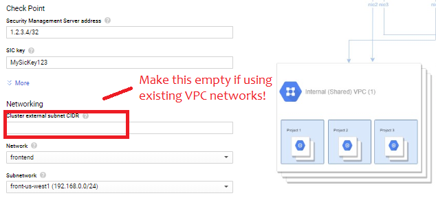
Networking
This is the real catch, and a pretty stupid one. The form fills out these three subnets:
“Cluster External Subnet CIDR” = 10.0.0.0/24
“Management external subnet CIDR” = 10.0.1.0/24
“1st internal subnet CIDR” = 10.0.2.0/24
If using an existing network, erase the pre-filled value and then select the appropriate networks in the drop-down menus like so:
Also, make sure all subnets have “Private Google Access” checked
Post-launch Configuration
After launch, access the gateways via SSH using public key and/or WebGUI to run through initial setup. The first step is set a new password for the admin user:
set user admin password
set expert-password
Since eth1 rather than eth0 is the management interface, I would recommend setting that accordingly:
set management interface eth1
I would also recommend adding static routes. The deployment will create static routes for RFC 1918 space via the management interface. If these need to be overridden to go via an internal interface the CLI command is something like this
set static-route NETWORK/MASK nexthop gateway address NEXTHOP_ADDRESS on
Before importing in to SmartConsole, you can test connectivity by trying to telnet to the security management’s server address on port 18191. Once everything looks good, don’t forget to save the configuration:
save config
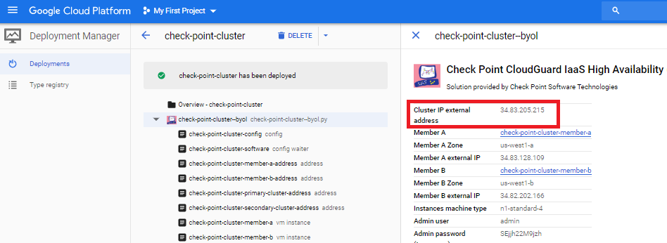
Cluster Creation
In SmartConsole, create a new ClusterXL. When prompted for the cluster address, enter the primary cluster address. The easy way to find this is look the the deployment result under Tools -> Deployment manager -> Deployments
Then add the individual gateways with the management interface. Walking through the wizard, you’ll need to define the type of each interface:
Set the first (external) interface to private use
Set the secondary (management) interface as sync/primary
Set subsequent interfaces as private use with monitoring.
Note the wizard tends to list the interfaces backwards: eth2, eth1, eth0
The guide lists a few steps to do within the Gateway Cluster Properties, several of which I disagree with. Instead, I’d suggest the following:
Under Network Management, VPN Domain, create a group that lists the internal subnets behind the Checkpoint that will be accessed via site-to-site and remote access VPNs
On the eth1 interface, set Topology to Override / This Network / Network defined by routes. This should allow IP spoofing to remain enabled
Under NAT, do not check “Hide internal networks behind the Gateway’s external IP” as this will auto-generate a NAT rule that could conflict with site-to-site VPNs. Instead, create manual NAT rules in the policy.
Under IPSec VPN, Link Selection, Source IP address Settings, set Manual / IP address of chosen interface
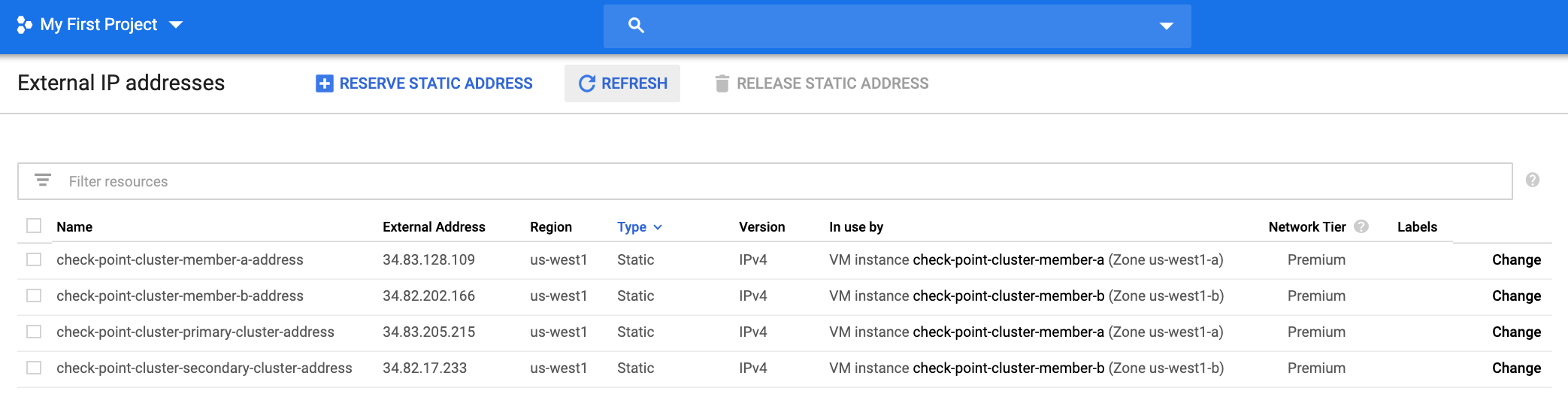
Do a policy install on the new cluster, and a few minutes later, the GCP console should map the primary and secondary external IP addresses to the two instances
Failover
Failover is done via API call and takes roughly 15 seconds.
On the external network (front end), the primary and secondary firewalls will each get external IP address mapped. CheckPoint calls these “primary-cluster-address” and “secondary-cluster-address”. I’d argue “active” and “standby” would be better names, because the addresses will flip during a failover event.
On the internal network (back end0, failover is done by modifying the static route to 0.0.0.0/0. The entries will be created on the internal networks when the cluster is formed.
Known Problems
The script $FWDIR/scripts/gcp_ha_test.py is missing
This is simply a mistake in CheckPoint’s documentation. The correct file name is:
$FWDIR/scripts/google_ha_test.py
Deployment Fails with error code 504, Resource Error, Timeout expired
Also, while the instances get created and External static IPs allocated, the secondary cluster IP never gets mapped and failover does not work.
Cause: there is a portion of the R80.30 deployment script relating to external IP address mapping that assumes the default service account is enabled, but many Enterprise customers will have default service account disabled as a security best practice. As of January 2020, the only fix is to enable the default service account, then redo the deployment.
StackDriver is enabled at launch, but never gets logs
Same issue as a above. As of January 2020, it depends on the default service account being enabled.
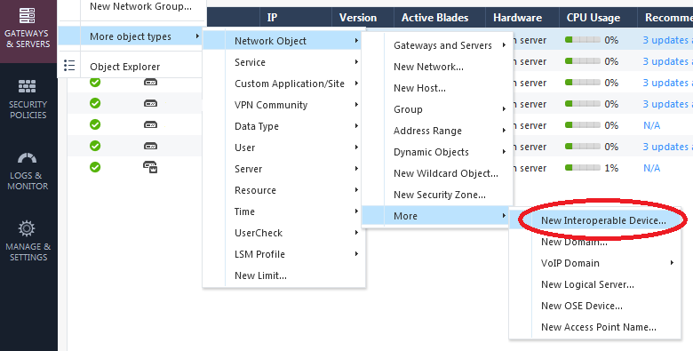
The first step is to create a new object with the public IP address of the other side of the tunnel. This is fairly well buried in the menus:
After that, create a new VPN “community” in Objects -> More object types -> VPN Community -> New Meshed VPN and walk through the wizard.
The main gotcha is watch out for weird default settings. In particular, AES-128 is disabled as encryption cipher for Phase 1. My guess is since it’s the most popular cipher for Phase 2, they go with the “mix ciphers” strategy. But personally I just like to use AES-128 for everything – it’s simple, fast, and plenty secure.
In both cases the configuration file is /etc/squid/squid.conf
I’d recommend setting these for better performance and improved stability:
# Allocate 2 GB of disk space to disk caching
cache_dir ufs /var/spool/squid 2048 16 256
# Cache files smaller than MB in size, up from default of 4 MB
maximum_object_size 256 MB
# Up max file descriptors from default of 1024 to 4096
max_filedesc 4096
Licensing costs start at just under $100 per user per year. For compute costs, these are common supported instance sizes in a typical region:
t2.micro 1 vCPU, 1 GB RAM, ~75 Mpbs = ~$100/yr
t2.small 1 vCPU, 2 GB RAM, ~125 Mbps = ~$200/yr
t2.medium 2 vCPU, 2 GB RAM, ~250 Mbps = ~ $400/yr
t2.large 2 vCPU, 8 GB RAM, ~500 Mbps = ~$800/yr
SSH to the IP address using the correct private SSH key and ‘openvpnas’ as the username
The setup wizard should start automatically. To run it again:
sudo su
/usr/bin/ovpn-init –ec2
To use the second (eth1) interface as the internal interface, get the IP address from AWS console and then edit /etc/netplan/50-cloud-init.yaml to add these lines ( (i.e. 192.168.101.123/255.255.255.0)
        eth1:
            dhcp4: no
            addresses: [192.168.101.123/24, ]
After saving the file, restart netplan and verify eth1 has the new IP address
sudo netplan apply
ifconfig eth1
To add internal static routes (for example, the RFC-1918 blocks) add these lines too:
            routes:
            - to: 192.168.0.0/16
                  via: 192.168.101.1
            - to: 172.16.0.0/12
                  via: 192.168.101.1
            - to: 10.0.0.0/8
                  via: 192.168.101.1
Then another restart netplan and verify the routes are working as entered
sudo netplan apply
netstat -rn
Set an initial password for the openvpn admin account via this command:
sudo passwd openvpn
Access the web gui at https://ip.address/admin/ logging in as openvpn with the password that was just set
New feature (finally!) in R80.30 is the ability to enabled Management data plane Separation, in order to have a separate route table for the management interface and all management related functions (Policy installation, SSH, SNMP, syslog, GAIA portal, etc).
Let’s assume the interface “Mgmt” has already been set as the management interface with IP address 192.168.1.100 and wants default gateway 192.168.1.1, and “eth5” has been setup as the dedicated sync interface:
set mdps mgmt plane on
set mdps mgmt resource on
set mdps interface Mgmt management on
set mdps interface eth5 sync on
add mdps route 0.0.0.0/0 nexthop 192.168.1.1
save config
reboot
After the box comes up you can verify the management route has been set by going in to expert mode and the the “mplane” command to enter management space:
> expert
[Expert@MyCheckPoint:0]# mplane
Context set to Management Plane
[Expert@MyCheckPoint:1]# netstat -rn
Kernel IP routing table
Destination  Gateway       Genmask         Flags MSS Window irtt Iface
169.254.0.0  0.0.0.0       255.255.255.252 U     0   0      0    eth5
192.168.1.0  0.0.0.0       255.255.255.0   U     0   0      0    Mgmt
0.0.0.0      192.168.1.1   0.0.0.0         UGD   0   0      0    Mgmt
Routes from the main route table relating to management can then be deleted, which makes the data plane route table much cleaner:
[Expert@MyCheckpoint:1]# dplane
Context set to Data Plane

[Expert@MyCheckPoint:0]# netstat -rn
Kernel IP routing table
Destination   Gateway       Genmask         Flags MSS Window irtt Iface
203.0.113.32  0.0.0.0       255.255.255.224 U     0   0      0    bond1.11
192.168.222.0 0.0.0.0       255.255.255.0   U     0   0      0    bond1.22
0.0.0.0       203.0.113.33  0.0.0.0         UGD   0   0      0    bond1.11
192.168.0.0   192.168.222.1 255.255.0.0     UGD   0   0      0    bond1.22