IPSec VPN Spoke Router using FQDN authentication

In a previous post I’d covered doing site-to-site IPSec tunnels on Cisco routers when one or both devices are behind NAT.  But what if multiple spoke routers have dynamic IP addresses? Or how about many behind the same NAT address? 

The solution is to have the spoke routers authenticate using FQDN hostname rather than IP address.  I’ve seen lots of examples which overly complicate how to do this.  It’s actually pretty simple and only requires minor changes.  Let’s assume the spoke routers have dynamic IPs and the hub has a static IP of 203.0.113.222…

IKEv1

Spoke Router

On spoke routers with IKEv1, simply replace  the “crypto keyring” statement with “crypto isakmp peer” to use FQDN authentication and IKE aggressive mode, like this:

hostname spoke1
! 
no crypto keyring MyHub
crypto isakmp peer address 203.0.113.222 [vrf InternetVRFName]
 set aggressive-mode password XXXXXXXX
 set aggressive-mode client-endpoint fqdn spoke1.mydomain.com 
!

Note the fqdn hostname doesn’t necessarily need to match the router’s hostname

IKEv2

Spoke Router

Set the Hub’s IP address and pre-shared key in an IKEv2 keyring:

crypto ikev2 keyring MY_IKEV2_KEYRING
 peer MyHub
  address 203.0.113.222
  pre-shared-key MySecretKey1234    ! Must be 16 chars or longer

The identity (hostname) in the IKEv2 profile via the identity local line:

hostname spoke1
!
crypto ikev2 profile SPOKE_IKEV2_PROFILE
 match address local interface GigabitEthernet0/0
 match identity remote address 203.0.113.222 255.255.255.255
 identity local fqdn spoke1.spokedomain.com
 authentication remote pre-share
 authentication local pre-share
 keyring local MY_IKEV2_KEYRING
 dpd 20 2 periodic 
!

IPSec profile:

crypto ipsec profile SPOKE_IPSEC_PROFILE
 set security-association lifetime kilobytes disable
 set pfs group14
 set ikev2-profile SPOKE_IKEV2_PROFILE
!

Tunnel Interface and static route to 10.0.0.0/8:

interface Tunnel1
 ip address 169.254.1.100 255.255.255.0
 ip tcp adjust-mss 1379
 keepalive 10 3
 tunnel source GigabitEthernet0/0
 tunnel mode ipsec ipv4
 tunnel destination 203.0.113.222
 tunnel protection ipsec profile SPOKE_IPSEC_PROFILE
!
ip route 10.0.0.0 255.0.0.0 Tunnel1

Hub Router

Each Spoke will need an entry. Use identity in the entry, not hostname

crypto ikev2 keyring SPOKES_IKEV2_KEYRING
 peer spoke1
  identity fqdn spoke1.spokedomain.com
  pre-shared-key MySecretKey1234
 !

The IKEv2 profile will be a bit different. The domain is used to match multiple spokes:

crypto ikev2 profile HUB_IKEV2_PROFILE
 match address local interface GigabitEthernet0/0
 match identity remote fqdn domain spokedomain.com
 identity local fqdn myhub.hubdomain.com
 authentication remote pre-share
 authentication local pre-share
 keyring local SPOKES_IKEV2_KEYRING
 dpd 10 2 on-demand
 virtual-template 1

The IPSec profile is almost the same but is responder-only (passive):

crypto ipsec profile HUB_IPSEC_PROFILE
 set security-association lifetime kilobytes disable
 set pfs group14
 set ikev2-profile HUB_IKEV2_PROFILE
 responder-only

Rather than a regular tunnel interface, a virtual template one is used:

interface Virtual-Template1 type tunnel
 ip unnumbered Loopback0
 tunnel source GigabitEthernet0/0
 tunnel mode ipsec ipv4
 tunnel destination dynamic
 tunnel protection ipsec profile HUB_IPSEC_PROFILE

Route Filtering and Aggregation in Hybrid Cloud scenarios (EIGRP -> BGP)

One of the challenges of cloud is route table limits .  For example, AWS has a limit of 100 per table.  This can pose a real challenge in hybrid cloud scenarios where the on-prem infrastructure can easily support hundreds or thousands of internal routes no problem, leaving you (aka “cloud guy”) responsible for performing filtering and aggregation.

Consider this scenario:

EIGRPtoBGPredistribution

The CSR1000v learns about 150 routes via EIGRP, mostly in RFC 1918 space:

D EX 10.4.0.0/16 [170/51307520] via 10.1.4.73, 00:05:02, Tunnel100
D EX 10.5.0.0/16 [170/51307520] via 10.1.4.61, 00:05:02, Tunnel100
D EX 10.6.8.0/22 [170/51307520] via 10.1.4.12, 00:05:02, Tunnel100
D EX 192.168.11.0/24 [170/52234240] via 10.1.4.88, 00:05:02, Tunnel100
D EX 192.168.22.0/23 [170/51829760] via 10.1.4.99, 00:05:02, Tunnel100
D EX 192.168.33.0/24 [170/51824640] via 10.1.4.123, 00:05:02, Tunnel100

So obviously we need need to do some filtering or summarization before passing the routes to the AWS route tables via BGP.

The quick and simple fix: summarize the 10.0.0.0/8 & 192.168.0.0/16 prefixes on the CSR1000v:

router bgp 65000
 bgp log-neighbor-changes
 !
  address-family ipv4 
  aggregate-address 10.0.0.0 255.0.0.0 summary-only  
  aggregate-address 192.168.0.0 255.255.0.0 summary-only
  redistribute eigrp 100
  neighbor 169.254.1.2 remote-as 65100
  neighbor 169.254.1.2 activate

Upon initial examination, this seems to work great.  Only the aggregate routes are passed to the BGP neighbors:

CSR1000v#sh ip bgp nei 169.254.1.2 advertised-routes | inc (10\.|192\.168)
*>  10.0.0.0         0.0.0.0       32768 i
*>  192.168.0.0/16   0.0.0.0       32768 i

But there’s a nasty surprise when the EIGRP neighbors are reset.  The “summary-only” option briefly stops working for about 20 seconds:

CSR1000v#sh ip bgp nei 169.254.1.2 advertised-routes | inc 10\.
*> 10.0.0.0      0.0.0.0              32768 i
*> 10.4.0.0/16   10.1.4.73  51307520  32768 ?
*> 10.5.0.0/16   10.1.4.61  51307520  32768 ?
*> 10.6.8.0/22   10.1.4.12  51307520  32768 ?
*> 10.7.12.0/22  10.1.4.52  51307520  32768 ?
*> 10.8.8.0/24   10.1.4.7   51307520  32768 ?
*> 10.9.0.0/24   10.1.4.41  51307520  32768 ?
*> 10.77.0.0/16  10.1.4.8   51312640  32768 ?

This exceeds the 100 route limit, and AWS will disable the BGP peering session for 5 minutes.

One fix is use filters instead of the “summary-only” option:

router bgp 65000
 bgp log-neighbor-changes
 !
 address-family ipv4
  aggregate-address 10.0.0.0 255.0.0.0
  aggregate-address 172.16.0.0 255.240.0.0
  aggregate-address 192.168.0.0 255.255.0.0
  redistribute eigrp 100
  distribute-list prefix SUMM_RFC_1918 out
!
ip prefix-list SUMM_RFC_1918 seq 10 deny 10.0.0.0/8 ge 9
ip prefix-list SUMM_RFC_1918 seq 20 deny 172.16.0.0/12 ge 13
ip prefix-list SUMM_RFC_1918 seq 30 deny 192.168.0.0/16 ge 17
ip prefix-list SUMM_RFC_1918 seq 99 permit 0.0.0.0/0 le 32

Another solution is simply don’t do EIGRP to BGP redistribution, and instead just advertise the RFC 1918 blocks with the network statement:

router bgp 65000
 bgp log-neighbor-changes
 !
 address-family ipv4 
  network 10.0.0.0
  network 172.16.0.0 mask 255.240.0.0
  network 192.168.0.0 mask 255.255.0.0
!
ip route 10.0.0.0 255.0.0.0 Null0 254
ip route 172.16.0.0 255.240.0.0 Null0 254
ip route 192.168.0.0 255.255.0.0 Null0 254

SSHing to an older Cisco ASA from a new Mac

Newer SSH clients such as on MacOS 10.14 (Mojave) may not want to use the old key sizes and cipher suites on an ASA.

One error message is about key exchange parameters:

no matching key exchange method found. Their offer: diffie-hellman-group1-sha1

Can fix this by using the older key exchange algorithm as an command line option:

ssh -oKexAlgorithms=+diffie-hellman-group1-sha1 username@myasa.com

This can then be fixed server-side on the ASA by configuring Group 14 (2048-bit keys)

ASA(config)# ssh key-exchange group ?
configure mode commands/options:
  dh-group1-sha1   Diffie-Hellman group 2
  dh-group14-sha1  Diffie-Hellman group 14
ASA(config)# ssh key-exchange group dh-group14-sha1

Likewise may get messages about cipher suites not matching:

no matching cipher found. Their offer: aes128-cbc,3des-cbc,aes192-cbc,aes256-cbc

Workaround is to specify ciphers as an option to SSH:

ssh -c aes128-cbc,3des-cbc username@myasa.com


IPSec VPNs on Cisco routers when both are behind NAT

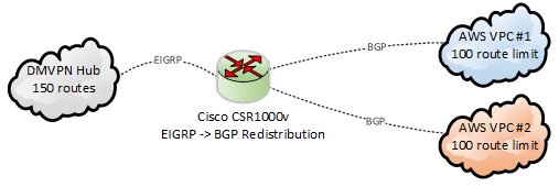
IPSec VPNs or really any site-to-site VPN works best when at least one of the sides or better yet both have Public IP addresses.  But what if one is behind NAT, or even both?  It gets increasing tricky to configure the correct IP addresses for authentication, and forward correct ports on protocols.  As I recently discovered, using IKEv2 and/or GRE further complicates things.  Consider this setup:

IPSecVPNsBehindNATs

Both routers are behind NAT/PAT firewalls without static 1-to-1 NATs configured.  There are still some requirements though:

  • Both firewalls must allow for protocol 50 passthrough for IPSec, or protocol 47 passthough if using GRE, which most do
  • At least one side must be forwarding ports udp/500 (isakmp) and udp/4500 (nat-t) to the router’s internet-facing interface so the connection can be established
  • Both routers need crypto ipsec nat-transparency udp-encapsulation enabled, which is the default setting.  

Let’s look at sample configs for each scenario.  These assume 1921 ISR G2 routers but IOS-XE configs should be exactly the same.

IPSec with ISAKMP / IKEv1

The is the simplest way to do it since only public IPs need to be referenced.

1) The ISAKMP portion:

crypto isakmp invalid-spi-recovery
crypto isakmp disconnect-revoked-peers
crypto isakmp keepalive 10 crypto isakmp nat keepalive 900 ! Policy supporting strong encryption crypto isakmp policy 100 encr aes 256 ! 256-bit AES encryption hash sha384 ! SHA-384 hashing authentication pre-share ! Using pre-shared keys lifetime 28800 ! 28000 seconds = 8 hours group 14 ! group 14 = 2048 bit key
! Backup policy supporting weaker encryption support for older devices crypto isakmp policy 200 encr aes ! 128-bit AES encryption hash sha ! SHA-1 hashing authentication pre-share ! Using pre-shared keys lifetime 28800 ! 28000 seconds = 8 hours group 2 ! group 2 = 1024 bit key ! FYI - default values are still des, sha, rsa-sig, 86400, group 1 :-O

2) And then pre-shared keys:

! Key for site 1 router
crypto keyring Site2
  local-address GigabitEthernet0/0
  pre-shared-key address 203.0.113.222 key 0 MySecretKey

! Key for site 2 router
crypto keyring Site1
 local-address GigabitEthernet0/0
 pre-shared-key address 198.51.100.111 key 0 MySecretKey

! Can also use "crypto isakmp key 0 MySecretKey address 1.2.3.4"

3) IPSec parameters.  For encryption, I like to just use 128-bit AES with either SHA-256 or SHA-1 signing with a group 2 (1024-bit) key to make the tunnel negotiation quick as possible.

! Create some IPSec Transform sets for ESP & 128-bit AES
crypto ipsec transform-set ESP_AES128_SHA256 esp-aes esp-sha256-hmac 
 mode tunnel
crypto ipsec transform-set ESP_AES128_SHA esp-aes esp-sha-hmac 
 mode tunnel

! Create IPSec profile
crypto ipsec profile MY_IPSEC_PROFILE
 set transform-set ESP_AES128_SHA256 ESP_AES128_SHA 
 set pfs group2    ! group 2 = 1024-bit key

Optional step: since the “client” side isn’t reachable on port udp/500, the “server” side may be configured as a responder.  This cuts down superfluous traffic, especially when the client is unreachable.

crypto ipsec profile IPSEC_PROFILE
 responder-only

5) The last step is build the tunnel interfaces.  For the “client” side:

interface Tunnel1000
 ip address 169.254.0.1 255.255.255.252
 ip tcp adjust-mss 1379
 keepalive 10 3
 tunnel source GigabitEthernet0/0
 tunnel mode ipsec ipv4
 tunnel destination 203.0.113.222
 tunnel protection ipsec profile IPSEC_PROFILE

Server side is exactly the same but with different IP addresses:

interface Tunnel1000
 ip address 169.254.0.2 255.255.255.252
 tunnel destination 198.51.100.111

Doing debug crypto isakmp on the server side while the tunnels come up shows the public IP address of the client.  Note the client’s random source ports.

ISAKMP (0): received packet from 198.51.100.111 dport 500 sport 14972 Global (R) MM_SA_SETUP
ISAKMP (1003): received packet from 198.51.100.111 dport 4500 sport 51597 Global (R) MM_KEY_EXCH
ISAKMP:(1003):SA has been authenticated with 198.51.100.111
ISAKMP:(1003):Detected port floating to port = 51597

We never see client’s private IP, but we do see the server side’s private IP at the end when the SA is finally built:

ISAKMP:(1003): Process initial contact,
bring down existing phase 1 and 2 SA's with local 192.168.2.222 remote 198.51.100.111 remote port 51597
ISAKMP: Trying to insert a peer 192.168.2.222/198.51.100.111/51597/, and inserted successfully

Can also see the other site’s private IP by examining the SAs once built:

Site1#show crypto isakmp peers 203.0.113.222
Peer: 203.0.113.222 Port: 4500 Local: 192.168.1.111
Phase1 id: 192.168.2.222

Site2#show crypto isakmp peers 198.51.100.111
Peer: 198.51.100.111 Port: 51597 Local: 192.168.2.222
Phase1 id: 192.168.1.111


IPSec with IKEv2

IKEv2 is new to me, but it was a surprise to see slightly different behavior when using NAT. Run through of the configuration:

1) Set some global IKEv2 parameters

crypto logging ikev2
crypto ikev2 nat keepalive 900
crypto ikev2 dpd 10 2 periodic

2) Create an IKEv2 Proposal and Policy

3) Keys are defined in the IKEv2 keyring, which has each site’s public IP address:

crypto ikev2 keyring MY_IKEV2_KEYRING
 ! Use this on site 1 router
 peer Site2
  address 203.0.113.222
  pre-shared-key MySecretKey1234    ! Must be 16 chars or longer
 ! Use this on site 2 router
 peer Site1
  address 198.51.100.111
  pre-shared-key MySecretKey1234    ! Must be 16 chars or longer

4) Create IKEv2 Profile

crypto ikev2 profile MY_IKEV2_PROFILE
 match address local interface GigabitEthernet0/0
 match identity remote address 192.168.0.0 255.255.0.0
 authentication remote pre-share
 authentication local pre-share
 keyring local MY_IKEV2_KEYRING
 dpd 20 2 periodic

This is where is gets weird because the “remote address” parameter needs to match the internal IP address(es) of the other sides.  The simple and lazy approach is use 0.0.0.0 since that will match anything.  The other option is use a different profile for each peer.

5) Add IKEv2 profile to the existing IPSec profile.  Note that doing so shouldn’t break IKEv1 clients as the IKEv2 stuff should just be ignored.

crypto ipsec profile MY_IPSEC_PROFILE
 set transform-set ESP_AES128_SHA256_TUNNEL ESP_AES128_SHA1_TUNNEL 
 set pfs group2
 set ikev2-profile MY_IKEV2_PROFILE

In the SAs, we can see our private IP,  but not the other side’s:

Site1#show crypto ikev2 sa remote 203.0.113.222
Tunnel-id Local                 Remote                fvrf/ivrf            Status
1         192.168.1.111/4500    203.0.113.222/4500    none/none            READY  
      Encr: AES-CBC, keysize: 128, Hash: SHA256, DH Grp:14, Auth sign: PSK, Auth verify: PSK
      Life/Active Time: 86400/30 sec

Site2#sh crypto ikev2 sa remote 198.51.100.111      
Tunnel-id Local                 Remote                fvrf/ivrf            Status 
1         192.168.2.222/4500    198.51.100.111/51597  none/none            READY  
      Encr: AES-CBC, keysize: 128, Hash: SHA256, DH Grp:14, Auth sign: PSK, Auth verify: PSK
      Life/Active Time: 86400/71 sec

BTW, if NAT-T has been disabled but is required by the other end, debug crypto ikev2 will show this:

Oct 12 19:53:08.620: IKEv2-ERROR:(SESSION ID = 1075,SA ID = 2): NAT is found but it is not supported.: NAT-T disabled via cli
Oct 12 19:53:08.620: IKEv2-ERROR:(SESSION ID = 1075,SA ID = 2):: NAT-T disabled via cli

IKEv2 Policies, Proposals, and Profiles on Cisco Routers

Just like “crypto isakmp policy”, the “crypto ikev2 policy” configuration is global and cannot be specified on a per-peer basis.  If there’s a mismatch, “debug crypto ikev2 error” will show something like this:

IKEv2-ERROR:(SESSION ID = 685,SA ID = 1):Expected Policies: : Failed to find a matching policyProposal 1: AES-CBC-128 SHA256 SHA256 DH_GROUP_2048_MODP/Group 14

There are two solutions.  The simplest is specify all possible encryption, integrity, and PFS parameters in a single proposal:

crypto ikev2 proposal MY_IKEV2_PROPOSAL 
 encryption aes-cbc-256 aes-cbc-192 aes-cbc-128 3des
 integrity sha512 sha384 sha256 sha1
 group 21 20 19 16 14 5 2

crypto ikev2 policy MY_IKEV2_POLICY 
 proposal MY_IKEV2_PROPOSAL

Alternately, write separate proposals, then list them in the policy by preference:

crypto ikev2 proposal HIGH 
 encryption aes-cbc-256 aes-cbc-192 aes-cbc-128 
 integrity sha512 sha384 sha256 
 group 21 20 19
crypto ikev2 proposal MEDIUM
 encryption aes-cbc-256 aes-cbc-192 aes-cbc-128 
 integrity sha256 sha1
 group 16 14
crypto ikev2 proposal LOW 
 encryption aes-cbc-128 3des
 integrity sha1 md5
 group 5 2
crypto ikev2 policy MY_IKEV2_POLICY 
 proposal HIGH
 proposal MEDIUM
 proposal LOW

It’s disappointing Cisco did not design things so policies could be associated with individual peers.   Imagine a router terminating VPNs to different business partners, where Partner A insists on AES256/SHA512/Group16, while Partner B is still doing 3DES/MD5/Group2.  You would write the policy with the most secure at the top, but there’s nothing to stop partner A from downgrading to partner B’s policy.  It’s a security concern, plus takes extra time to negotiate.

Palo Alto Firewalls supports different ISAKMP policies on a per-IKE gateway basis and it’s one of the reasons I’ve really preferred them for Site-to-Site VPNs over the years.

SYSMGR-2-CFGWRITE_ABORTED_CONFELEMENT_RETRIES

15 minutes on a Cisco Nexus 9k and already found a cute bug.

SYSMGR-2-CFGWRITE_ABORTED_CONFELEMENT_RETRIES: Copy R S failed as config-failure retries are ongoing. Type "show nxapi retries" for checking the ongoing retries
# show nxapi retries
#1. Dn: sys/vpc/inst/dom/keepalive, Operation: modify, Src: vpc bmp: 0x4.

Quickest stupid work-around I could find:

# copy running-config bootflash:latestconfig.txt
# copy bootflash:latestconfig.txt startup-config 
# reload

And there’s a similar looking bug:

# copy run start
[########################################] 100%
Configuration update aborted: request was aborted


Authentication to Synology Directory Server (LDAP Server)

Upon configuring Directory Server the Synology will provide something like this:

The password configured is password for the ‘root’ user

Configuration for Cisco ASA / AnyConnect

aaa-server SYNOLOGY protocol ldap
aaa-server SYNOLOGY (Inside) host 192.168.1.100
 ldap-base-dn dc=myserver,dc=mydomain,dc=com
 ldap-scope subtree
 ldap-naming-attribute uid
 ldap-login-password <root user password>
 ldap-login-dn uid=root,cn=users,dc=myserver,dc=mydomain,dc=com
 server-type auto-detect

Configuration for FortiGate GUI

  • Common Name Identifier = uid
  • Distinguished Name = cn=users,dc=myserver,dc=mydomain,dc=com
  • Bind Type = Simple

Configuration for F5 BigIP

Need to change Authentication from ‘Basic’ to ‘Advanced’ to set Login LDAP attribute

  • Remote Directory Tree: dc=myserver,dc=mydomain,dc=com
  • Scope: Sub
  • BIND DN: uid=root,cn=users,dc=myserver,dc=mydomain,dc=com
  • Password: <root user password>
  • User Template: uid=%s,cn=users,dc=myserver,dc=mydomain,dc=com
  • Login LDAP Attribute: uid

To use Remote Role Groups:

Attribute String: memberOf=cn=users,cn=groups,dc=myserver,dc=mydomain,dc=com


EEM Script to Generate Show Tech & Auto Reboot a router

While working through my CSR1000v stability woes, I had the need to automatically generate a “show tech” and then reboot a router after an IP SLA failure was detected.  It seemed fairly easy but I could never get the show tech fully completed before the EMM script would stop running, and the reboot command never worked either.

Posting on Reddit paid off as user caught the problem: EEM scripts by default can only run for 20 seconds.  Since a “show tech” can take longer than this, the subsequent steps may never be processed.  The solution is increase the runtime to say 60 seconds to guarantee the show tech completes:

! Create and run IP SLA monitor to ping default gateway every 5 seconds
ip sla 1
 icmp-echo 10.0.0.1 source-interface GigabitEthernet1
 threshold 50
 timeout 250
 frequency 5
!
ip sla schedule 1 life forever start-time now
!
! Create track object that will mark down after 3 failures
track 1 ip sla 1
 delay down 15 up 30
!
! Create EMM script to take action when track state is down
event manager session cli username "ec2-user"
event manager applet GatewayDown authorization bypass
 event track 1 state down maxrun 60
  action 100 cli command "en"
  action 101 cli command "term len 0"
  action 110 syslog priority notifications msg "Interface Gi1 stopped passing traffic. Generating diag info"
  action 300 cli command "delete /force bootflash:sh_tech.txt"
  action 350 cli command "show tech-support | redirect bootflash:sh_tech.txt"
  action 400 syslog priority alerts msg "Show tech completed. Rebooting now!"
  action 450 wait 5
  action 500 reload

Words of caution deploying the CSR1000v with DMVPN on AWS t2.medium instances

The last 6 months of my life have been living hell thanks to Cisco.  I was assigned a relatively simple project of configuring some CSR1000v virtual routers in Amazon Web Services for the purpose of DMVPN spoke termination.  It has been miserable thanks to the unprecedented number of bugs on a product that’s over 5 years old.

Adding to the confusion, the primary issue is specific to the t2.medium instance type.  Since these are by far the cheapest instances and support up to 250 Mbps throughput (more than adequate for most organizations) I suspect I’m not the first to encounter problems, but am the first to find the root cause.

Problem #1 – They crash!

We launched the first batch of CSR1000vs in January 2019.  I had meant to tell the person launching them to try and do very 16.6 since that was the company standard for IOS-XE, but they defaulted to 16.9.1.  However, everything seemed fine as basic configuration and connectivity tests were successful.  But a few days after launching some test instances, I noticed the routers had rebooted unexpectedly.   Fortunately this was easy to diagnose since there were crash files I could provide TAC.  The bug was this:

CSCvk42631 – CSR1000v constantly crashes when processing packets larger than 9K

Since most instances launched in AWS have a 9001 Byte MTU by default, going with this version was a non-starter.  No problem, 16.9.2 was already available so that’s an easy fix….or so I thought.

Problem #2 – They stop passing traffic

I copied over 16.9.2 and 16.6.5 software images.  Initially I just booted 16.9.2 to verify they no longer crashed.  Welp, now we have a different problem.

The systems team said they had lost connectivity in the middle of the day.  I tried logging in to the CSR1000v via its external internal and could not access it.  However, I was able to access the peer router and then hop in via the private interface.  I saw that the external interface had “no ip address assigned”, which would indicated it lost connectivity to the DHCP server and failed renewal.

Around this time I started scanning Reddit.  A user mentioned trying to roll out CSR1000vs on t2.mediums with DMVPN configured and having similar stability woes.  Cisco was of little use, but Amazon support blamed it on CPU micro-bursts likely caused by route changes.  Switching the instances from t2.medium to c4.large resolved the issue.  This really didn’t make sense to me, but I could see cases where bursts were triggering a near exhaustion of CPU credits.  I looked at CloudWatch and indeed would see cases of the CPU credit balances suddenly dropping, but could not tell if this was the root cause or simply a secondary symptom of it not passing traffic.  After doing some reading on this topic I switched the instances to  T2 unlimited, but even after a reboot, there was no behavioral change.

t2Medium_CPUCredits

I also followed the CPU red herring trail for a bit longer and found this

Features—Cisco IOS XE Fuji 16.7.1

The following new software features are supported on the Cisco CSR 1000v for Cisco IOS XE Fuji 16.7.1.
- Templates for vCPU allocation and distribution—including the Control Plane heavy template.

Sure enough, you can see lower on average CPU usage when upgrading to 16.7 and newer trains

csr1000v_cpu_166_vs_167.png

But this is still overall very low CPU usage that should certainly not be causing an interface to stop passing traffic entirely.  So we’re back to square one.

I’m now caught between a rock and a hard place because 16.6.4 and 16.9.1 will cause the router to crash and reboot, but 16.6.5 and 16.9.2 will cause one of the interfaces to stop passing traffic.  The work-around I came up with was create IP SLA monitors to ping the adjacent gateways combined with an EEM script to auto-reboot upon detection.

Update April 26th 2019: We have a bug ID!  CSCvp48213

Update May 24th 2019: We have a root cause.  It’s a problem related to Generic Receive Offload (GRO) being enabled at the Linux kernel level.  This will be fixed in 16.9.4 or 16.6.6, which are due out towards the end of 2019 😐

Update June 6th 2019:  I went back at the original bug and have a theory what the problem is.  Looks like between 16.9.1 and 16.9.2 they lowered the MTU at the vNIC level to 1500 bytes:

Router#show platform software system all
VNIC Details
============
Name Mac Address Status Platform MTU
GigabitEthernet1 12bf.4f69.eb56 UP 1500
GigabitEthernet2 1201.c32b.1d16 UP 1500

To me, this seems much more like a hackish workaround that a fix.

Problem #3 – Internal traffic is fine, but Internet traffic is painfully slow

After working through the above two problems, I finally got time to try upgrading to 16.10.1b.  Surprisingly, this fixed the stability problem.  No more crashes, no more freeze-ups.  But upon doing more detailed testing, we found a new issue – when using the CSR1000v for internet access (via NAT), speeds were horribly slow.  I would get 125 KBps at best despite having verified the 100 Mbps license was installed and “platform hardware throughput level” was configured and enabled.

ubuntu@ip-10-13-22-161:~$ curl ftp://ftp.freebsd.org/pub/FreeBSD/releases/i386/i386/ISO-IMAGES/11.2/FreeBSD-11.2-RELEASE-i386-bootonly.iso > /dev/null
 % Total % Received % Xferd Average Speed Time Time Time Current Dload Upload Total Spent Left Speed
100 261M 100 261M 0 0 30733 0 2:28:55 2:28:55 --:--:-- 92708

Very much seemed like a licensing issue since 125 KBps = 1 Mbps which is the speed set in evaluation mode.  But speeds going over an IPSec VPN tunnel were up to 50 Mbps, which made no sense.

Opened another TAC case and got nowhere.  Once again I’m on my own, so I desperately started reading release notes and find this:

CSCvn52259 – CSR1Kv:Throughput/BW level not set correctly when upgrade to 16.10.1 .bin image with AWS/Azure PAYG
We’re using BYOL rather than PAYG, but this seemed very suspicions since I had indeed upgraded from 16.9.X to 16.10.1.  Sure enough, I do another upgrade to 16.11.1a and speeds now jump to 100 Mbps!  This is also fixed in 16.10.2

I would suspect this has something to do with Smart licensing, since it is mandatory starting with version 16.10


tviUezPkMB8zTzccFGi3M661t4vQJL25Ic5ytcPFMr0


Using Cisco Smart Licensing on IOS-XE

Converting PAKs to Smart Licenses

First, convert existing PAKs to smart licensing by going to the Traditional Licensing Portal, selecting the PAK, and from the “Smart Accounts” tab, select “Convert selected PAKs to smart licensing”.

SmartLicensingConvert

Note that PAKs entered via the Smart Licensing portal are not automatically converted.

Router CLI Configuration

In config mode, enable DNS resolution on the device to communicate w/ Cisco

ip domain-lookup
ip name-server 8.8.8.8

Configure Smart Call-home

service call-home
call-home
 contact-email-addr me@mydomain.com
 profile "CiscoTAC-1"
  active
  destination transport-method http
  no destination transport-method email

In software versions prior to 16.12, Smart Licensing will need to be enabled in config mode:

license smart enable

Creating and Applying Smart License Tokens

Visit the Smart Licensing Portal, select the PAK, and generate a token.

SmartLicensingNewToken

In enable mode, paste the token in via CLI:

license smart register idtoken XXXXXXX

Verify token has been accepted and registration successful

show license status

Finish by configuring and verifying any features added by the license

platform hardware throughput level mb 250
Wait for 250M license request to succeed

license boot level ax
% use 'write' command to make license boot config take effect on next boot

Router# show platform hardware throughput level 
The current throughput level is 250000 kb/

Re-initializing Licenses after Software Downgrade

When upgrading or especially downgrading IOS-XE versions, you’ll typically see an error the that license has already been used:

Router#show license status
Smart Licensing is ENABLED

Registration:
  Status: UNREGISTERED - REGISTRATION FAILED
  Export-Controlled Functionality: Not Allowed
  Initial Registration: FAILED on Mar 20 01:22:15 2019 GMT

Failure reason: The product regid.2013-08.com.cisco.CSR1000V,1.0_1562da96-9176-4f99-a6cb-14b4dd0fa135 and sudi containing udiSerialNumber:9PFNTCW3Y0L,udiPid:CSR1000V has already been registered.

Or red herring messages like this:

%SMART_LIC-3-AUTH_RENEW_FAILED: Authorization renewal with the Cisco Smart Software Manager or satellite : Response error: Data and signature do not match 
%SMART_LIC-3-AUTH_RENEW_FAILED: Authorization renewal with the Cisco Smart Software Manager or satellite : NULL 
%SMART_LIC-3-AUTH_RENEW_FAILED: Authorization renewal with the Cisco Smart Software Manager or satellite : verify RESP fail

Simple fix: just re-install a token with the “force” option at the end, i.e:

license smart register idtoken XXXXXXX force